HTK-ZJ11 Bearing Conditions Test Jig
- Product Details
- Company Profile
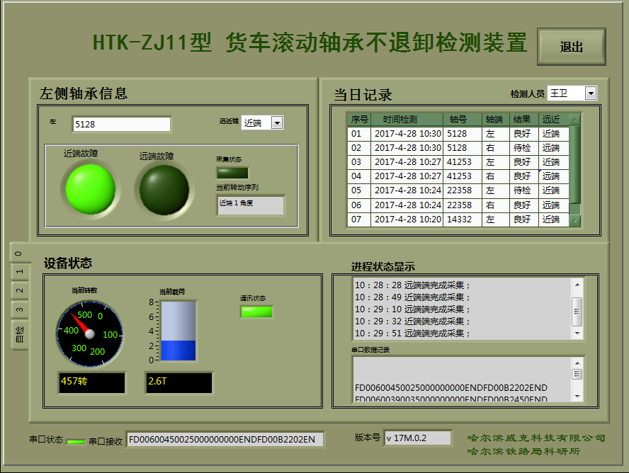
HTK-ZJ11 bearing conditions test jig is installed at depot workshop to detect bearing conditions when the bearings are fixed on wheelset. The jig can rotate the cup of the bearing to generate relative movement between bearing components. The movement will generate vibration signals which will be collected by acceleration sensor for analysis carried with special algorithm developed by HTK to pick any defects that may occur on the components. The defect that the jig can pick includes spall and scratches on cup, cone and roller.
General
HTK-ZJ11 bearing conditions test jig is installed at depot workshop to detect bearing conditions when the bearings are fixed on wheelset. The jig can rotate the cup of the bearing to generate relative movement between bearing components. The movement will generate vibration signals which will be collected by acceleration sensor for analysis carried with special algorithm developed by HTK to pick any defects that may occur on the components. The defect that the jig can pick includes spall and scratches on cup, cone and roller.
The detecting duration for each wheelset is 3 minutes.
2. Composition
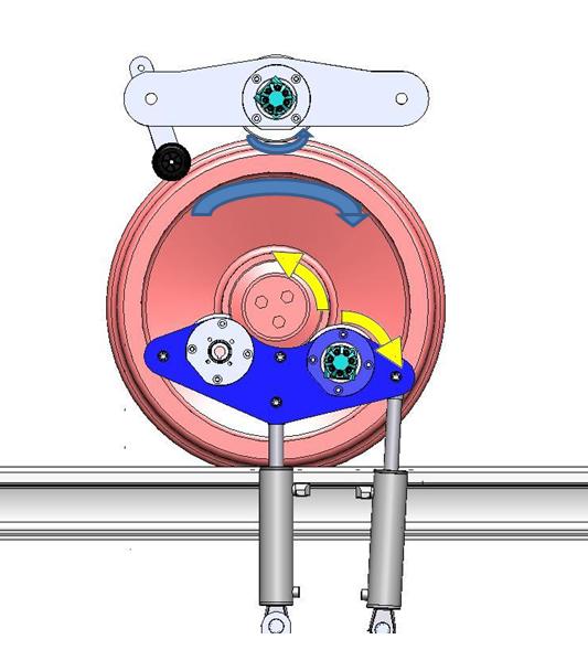
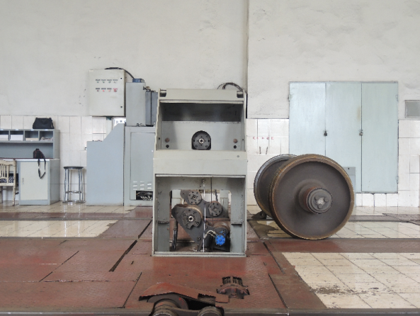
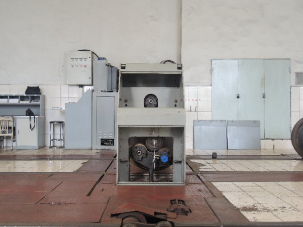
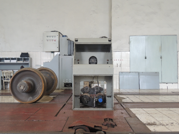
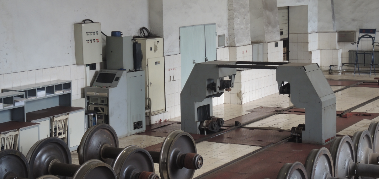
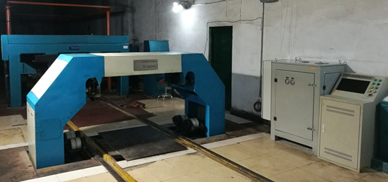
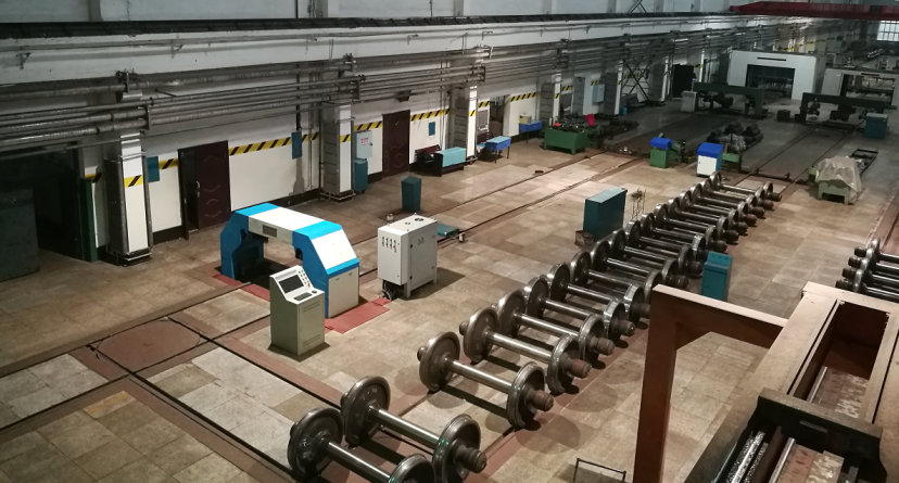
The system consists of wheelset jig, control console, hydraulic unit, vibration signal collector and data processing unit. Please see below figure.
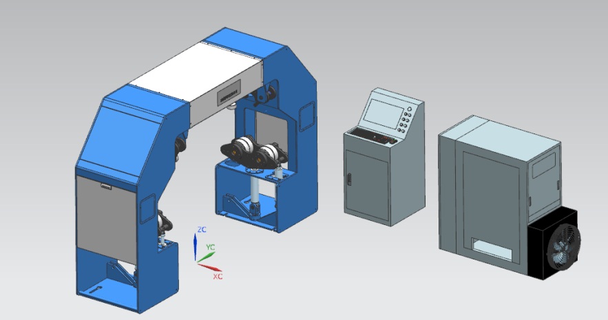
The wheelset jig is a platform where the test will be carried. The mechanism is provided for lifting wheelset and rotating the bearing.
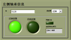
The control console provides operator to control the jig movements, input wheelset parameter, review detection results and retrieve history records.
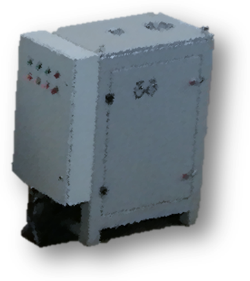
The hydraulic unit provides force to lift and rotate the wheelset as well as to add loads on the bearing. The unit consists of cylinders and motors. A power distributor provides control of power supply.
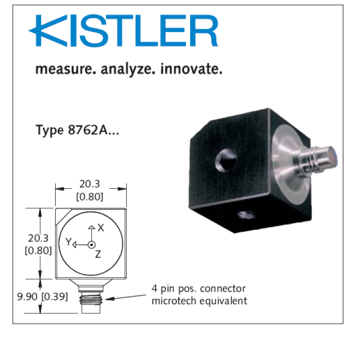
The vibration signal collector consists of acceleration sensor, cable, AD board and an IPC.

The acceleration sensor is a product from KISTLER.
The data processing unit provides man-machine dialog interface. It contains algorithm to process the collected bearing vibration signal aiming to pick bearing defects. The unit also provides detection control, supports generating alarms and polling history data.
How it works
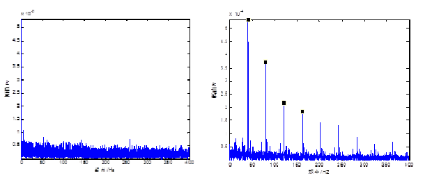
During the jig rotating the cup of the bearing, if any defect occurring on the component of the bearing, it will generate impact between components. The impact can be collected by acceleration sensor in form of attenuated pulse with high and cyclical frequency and amplitude. The algorithm will identify the impact frequency and amplitude and pick the defect according to characteristics of the frequency and amplitude.
The left diagram below shows the frequencies of a good bearing. The right diagram shows the frequencies of a bearing with defect.
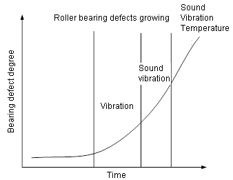
A defect in a roller bearing generates unique characteristic signal when it is in different growing stages. In the early stage, the defect’s signal is usually in form of vibration
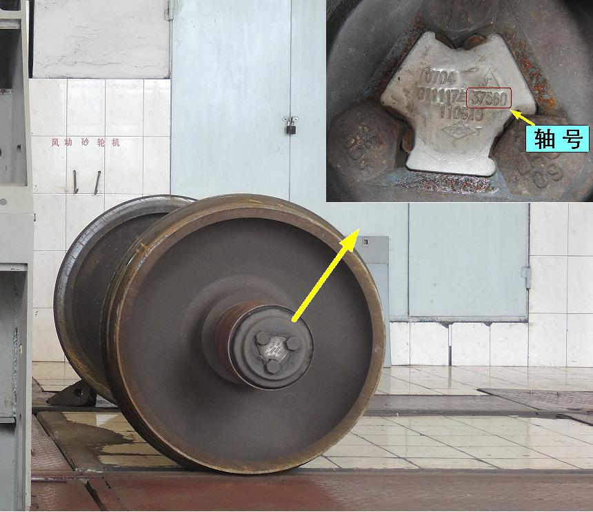
Step 1 | Push wheelset in the jig |
|
Step 2 | Input wheelset parameters |
|
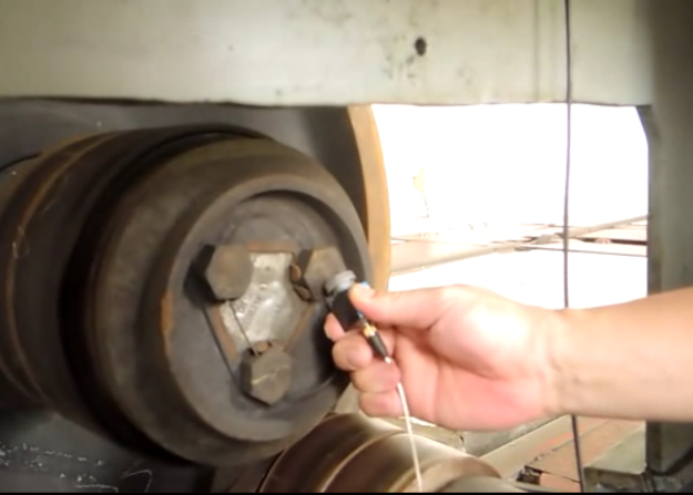
Step 3 | Install acceleration sensor |
|
Step 4 | Testing |
|
Step 5 | Display detecting results |
|
Step 6 | Taking off acceleration sensor and pull out wheelset |
|
History installations
So far, three units of HTK-ZJ11 bearing conditions test jigs have been installed from 2011.
Pilot installation at Harbin Depot in 2011 |
|
Second installation at RHL depot in Jan 2017 |
|
Third installation at JMS depot in Sept 2017 |
|
Defective bearings picked
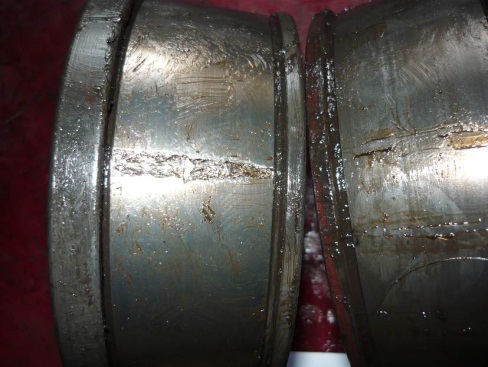
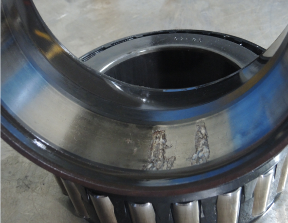
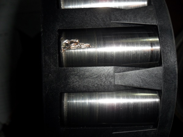
Below pictures show the defects picked by the jig. The history performance proved that there is no missing alarm.
Description | Defect |
Bearing No. 13010123504 Picked at Harbin depot in 7 Jan. 2013 Defect: spall on cone and roller
| |
Bearing No. 13041110504 Picked at Harbin depot in 12 Apr. 2013 Defect: spall cup
|
|
Bearing No. 15110477504 Picked at Harbin depot in 23 Nov. 2015 Defect: spall roller
|
|


 Free Member
 0
0 Chinese
Supplier